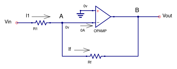
DC Inverting Amplifiers Using Opamps
01/2016 by D. Nutter
Introduction
For opamps, the voltage at the + and - inputs are equal, so with the + input attached to ground, the voltage at the - input is 0 volts. Also, the current into the + and - inputs of the opamp is 0 amps (or close enough to be considered an ideal opamp).
Current
The KCL equation for the opamp at node A is below. Note the current into the - opamp input is 0 amps.

Inverting Amplifier Equation Derivation by Node Method
The derivation of how to calcuate the amplifier output given a DC input and input and feedback resistor values is listed below. The voltage at node A is 0 volts since the voltage at the + input is 0 volts. Note that Vout is negative, therefore the label “inverting amplifier”. The gain of the DC opamp circuit is (Rf / R1).
